Design connections between structural elements seamlessly with CYPE Connect
2025.a Version
Compatible with the Open BIM workflow and other CYPE programs, it can import BIM models, generate detailed documents and optimise the design of connections using the finite element method, which includes the powerful OpenSees© analysis engine
Its intuitive interface and ability to create connection libraries improve the efficiency of the structural design process
Our design program uses the finite element method which includes the OpenSees© analysis engine

Connections between structural elements are crucial to ensure the safety and integrity of any project. They require accurate analysis and, thanks to technological advances, very innovative solutions have emerged to address them. These tools have managed to integrate seamlessly into the current software ecosystem and are compatible with many Open BIM workflows.
Easily design connections between structural elements
To deal with connections between structural elements, we offer you CYPE Connect, which can import BIM models, generate detailed documents and optimise the design of connections using the finite element method that includes the OpenSees© analysis engine. This tool provides precision and efficiency in structural design and helps you to design and check the connections between different structural elements of a project. In addition, CYPE Connect offers the possibility of creating detailed sheets of each connection from the BIM model.
The program interface is intuitive and preserves the style of other CYPE modelling tools. It integrates into our ecosystem perfectly and is compatible with the Open BIM workflow. The modelling process is sequential, so the steps required to model a connection can be recorded and reproduced for other similar connections. This allows users to create a library of pre-designed connections to speed up the design process.
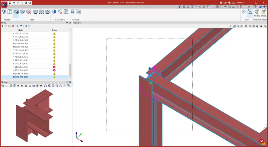
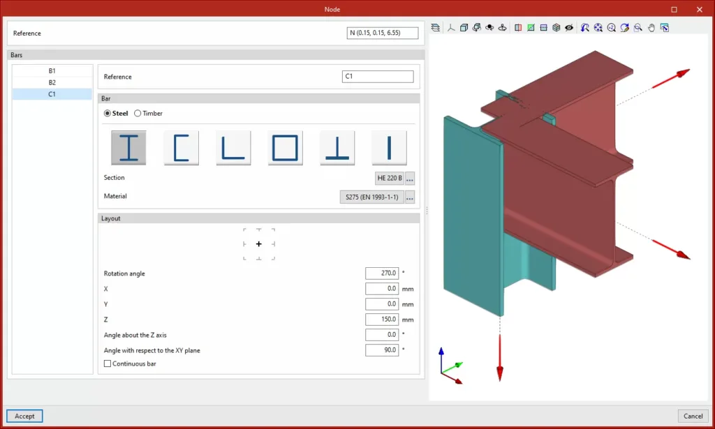
It is important to understand that a node in structural engineering is a group of bars, each of which may be made of different materials or have different geometries and which meet at a certain point. Once the node is defined, the next step is to model and analyse the connection.
How to create connections with CYPE Connect
Crear uniCreating connections in CYPE Connect is an intuitive and flexible process that starts by selecting the node to be designed from the “List of nodes”. You’ll be able to create a detailed 3D model of the connections between beams, columns and other parts of the structure, as well as enter loads manually or import them from a structural analysis BIM program, giving you a clear and accurate view of the connection design at all times.
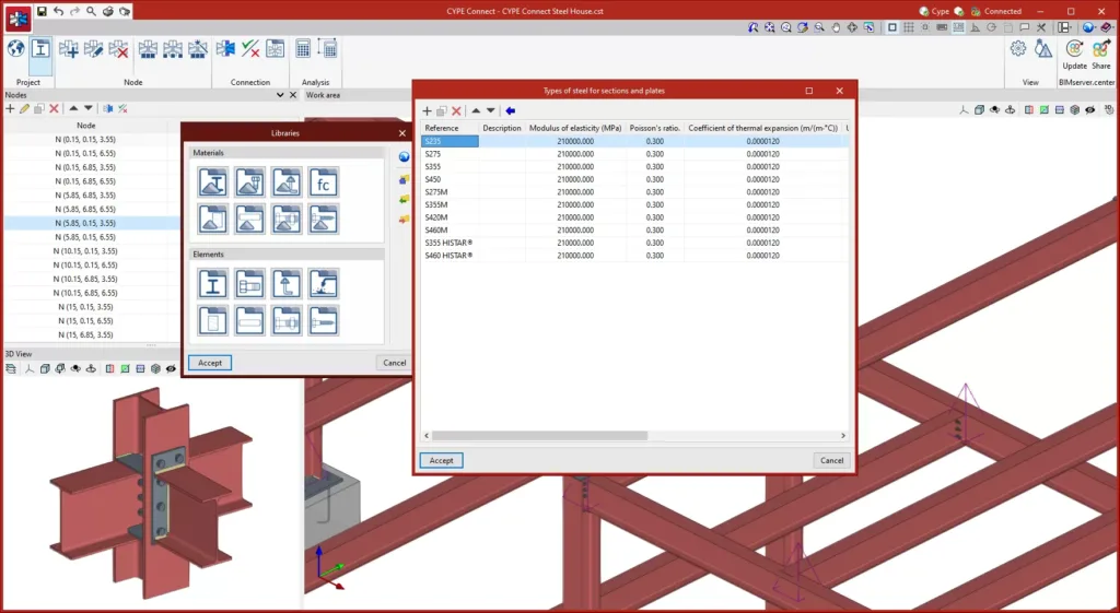
To resolve a node, CYPE Connect has different tools available, which vary depending on the type of node and the materials used. Connections can be resolved using different elements such as plates, welds, bolts, anchoring elements, dowels, and much more. Depending on the specific type of connection, different operations will be used, such as creating openings, placing anchors, applying bolts or trimming.
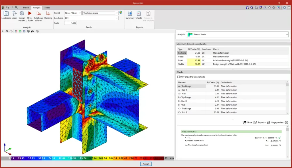
Once the connection is defined with all its operations and settings, the analysis is carried out. In CYPE Connect, this is done by simply selecting the analysis option, after which the software performs the necessary analyses and checks to verify the integrity and regulatory compliance of the designed connection. These checks can also be carried out according to the criteria of different codes.
The program has several options for visualising and evaluating the results of the analysis. One of these is the maximum utilisation coefficient, which shows the elements of the connection in different colours according to their use percentage. This visual representation makes it possible to identify critical areas of the connection quickly. By selecting a specific element, its detailed checks are displayed, including deformations, weld strength, and bolt checks.
Furthermore, users can visualise the Von Mises stress and strain, as well as the displacements of the connection. These graphical representations analyse the structural behaviour of the connection. For a more detailed analysis, the program generates design reports including summaries of components, applied loads, code checks and anchor forces.
With CYPE Connect you can also generate detailed sheets of the connections using the “Sheets” tab. With tools for inserting views, dimensioning and tagging elements, CYPE Connect allows you to create accurate documents for your connections between structural elements quickly and easily.
Optimise your connections between structural elements
Our tool stands out for its precision in finite element analysis, generating detailed models that respect the real layout of the connections. This feature ensures highly reliable results that can be applied directly to your project. In addition, it offers a wide variety of materials, allowing you to work with structures made of steel, timber or combinations of both. Thanks to this flexibility, you can cover a wide range of projects and structural needs.
On the other hand, the fact that CYPE Connect can be integrated with other CYPE programs such as CYPECAD and CYPE 3D provides a smooth workflow. Furthermore, its compatibility with the BIMserver.center platform makes it easier for users to collaborate and exchange information. It also gives you the flexibility to create nodes and enter forces manually or import BIM structural models. The modelling and analysis process is structured in three main tabs: “Model“, “Analysis” and “Sheets“. The program adapts to your needs and allows you to generate detailed drawings and complete documents of the designed connections.
In short, with CYPE Connect we provide you with a tool for analysing connections in steel and timber structures. Its integration with the CYPE ecosystem, its compatibility with the Open BIM workflow, and its capacity to generate detailed documents make it a complete solution for professionals in the industry.

