10 examples that show how CYPE programs make you more productive
Automating repetitive tasks is key to working efficiently. CYPE software makes this possible for analyses, designs and installations
Do your technical documents accurately reflect your model? With CYPE, drawings and reports are generated directly from the project
The connection between programs such as CYPE 3D, CYPE Connect and StruBIM Steel guarantees a seamless workflow, from design to fabrication
CYPE’s programs are designed to automate repetitive tasks, reduce errors and speed up the development of projects in the AEC industry. Here are ten examples of features that show why working with CYPE means working with greater efficiency, technical accuracy and time savings.
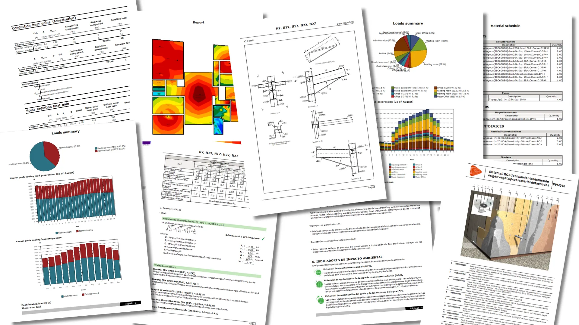
1. Automatic generation of reports and documents
One of the great advantages of working with CYPECAD or CYPE 3D, for example, is that once the analysis of the structure has been completed, the specialists will have all the reports and supporting documents available in a single click. From regulatory check reports to load, force and design tables, all the necessary documents for the technical justification of the project are generated automatically, saving time and guaranteeing the consistency between the model and the deliverable documents.
This ability is not exclusive to these three programs. The automatic generation of technical documents is part of CYPE’s DNA and is present in many other solutions in our portfolio, which always aim to maximise the designer’s productivity.
Various examples of reports generated with several programs in the CYPE suite
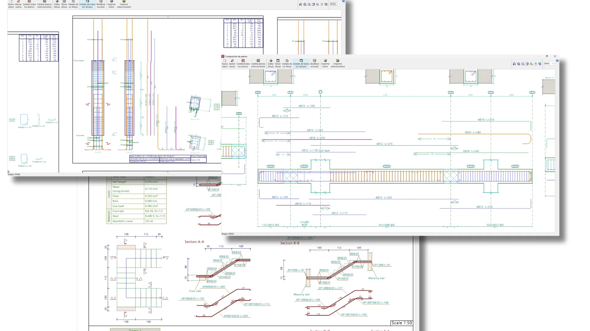
2. Automatic generation of drawings and details in DWG, PDF, DXF, etc.
CYPECAD is once again a great example of productivity, where structural drawings are automatically generated with all the necessary information: floor plans, foundations, reinforcement, sections, construction details, material reports, etc. Users can edit the drawings directly in the program itself (for example, modify dimensions, scale texts or change line thicknesses) or export the drawings to formats such as DWG, DXF or PDF for detailed editing in other CAD programs.
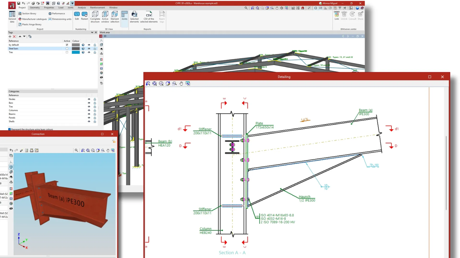
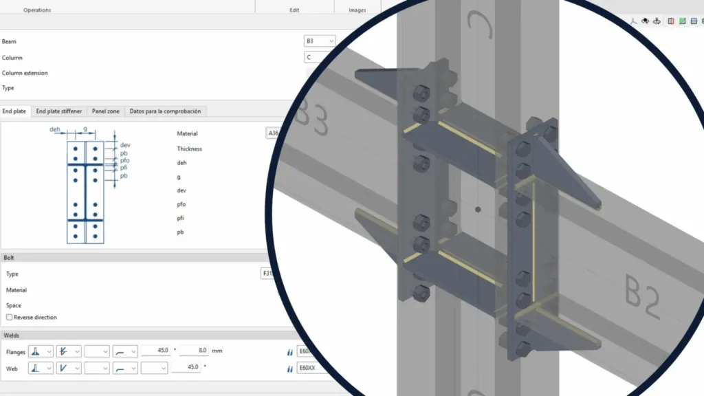
In CYPE 3D, in addition to the general drawings of the steel structure, the program automatically generates drawings of connections between structural steel elements from the results of the structural analysis. These drawings include plates, bolts, welds, dimensions, assembly references and other construction details that accurately reflect the analysed behaviour of each connection. All of this makes it possible to speed up both fabrication and assembly on site, minimising errors and ambiguous interpretations.
This philosophy is the same for many other CYPE programs, from MEP systems to architecture.
Drawings generated from a project developed in CYPECAD
Details of a connection designed in CYPE 3D
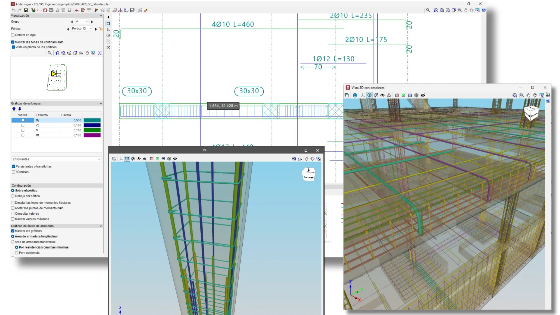
3. Automatic generation of reinforcement in reinforced concrete structures with CYPECAD
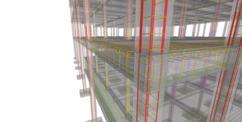
After the structural analysis, CYPECAD automatically designs the longitudinal and transverse reinforcement of beams, columns, slabs, walls and foundations, complying with the applicable codes and considering the efficiency and economy criteria. For example, in a joist floor slab, the program analyses the anchor lengths, overlaps, covers and stirrup spacings, and generates the reinforcement drawings ready for construction.
In BIM models created with CYPE, the reinforcement of a reinforced concrete structure no longer needs to be re-modelled – CYPE does it for you!
Different types of details generated with CYPECAD
4. Automatic design of steel sections in CYPE 3D
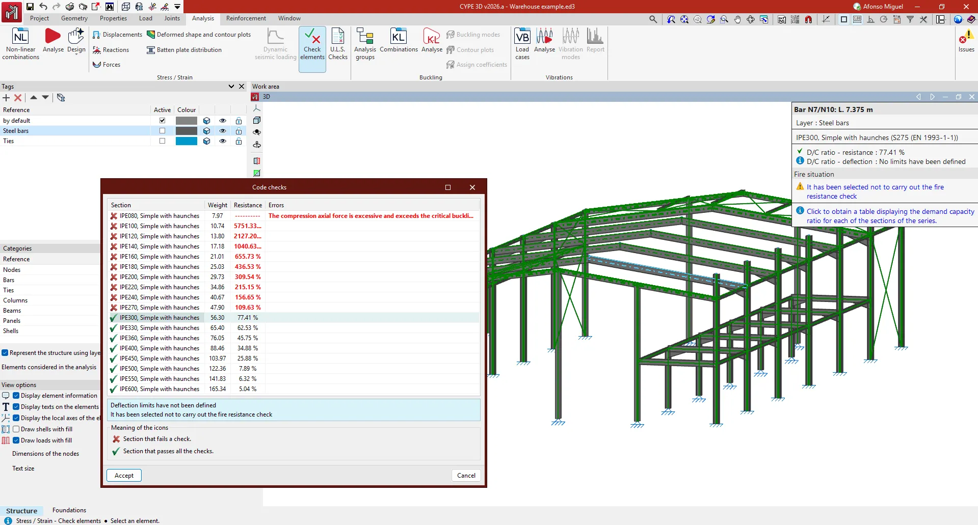
CYPE 3D can model and analyse 3D steel structures quickly and accurately. Once the geometry and loads have been defined, the program automatically selects the appropriate sections for each bar, verifying their behaviour with respect to the forces and boundary conditions. This automation facilitates decision-making in preliminary phases and avoids manual iterations.
By means of the graphic results and the table with the selected section series, CYPE 3D displays the most suitable section, optimising the structural project
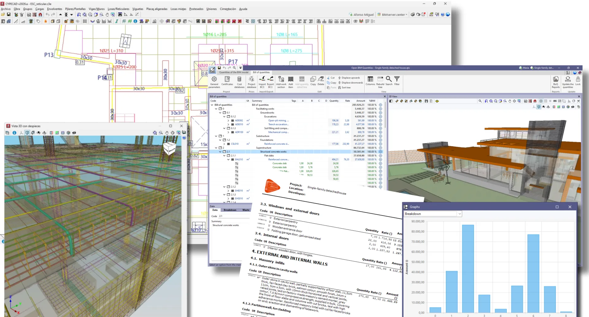
5. Efficient generation of the bill of quantities and construction documents with Open BIM Quantities
The models, defined using the IFC standard and developed in CYPECAD or CYPE Architecture, can be directly connected to Open BIM Quantities to establish customised quantity criteria, converting the data of the BIM model elements into detailed and precise items. This linking can generate a multitude of reports such as quantities, bills of quantities, specifications, environmental impact indicators, certificates, among others. These qualities optimise and facilitate the economic planning and project documents.
6. Automatic layout of plumbing systems in CYPEPLUMBING (as of version 2026)
As of version 2026, the Water Systems tab in CYPEPLUMBING can automatically generate the layout of the plumbing networks (cold water and domestic hot water) based on the consumption points defined in the architectural model. The program identifies the sanitary appliances (washbasins, showers, toilets, etc.) and inserts the necessary pipes, respecting the minimum slopes, the regulatory diameters and the pressure and flow criteria.
7. Automatic lighting distribution in CYPELUX (as of version 2026)
As of version 2026, CYPELUX can automatically distribute lighting fixtures previously selected by the designer in the building spaces, or even throughout the entire building on a massive scale. The program places them according to the user-defined criteria (mounting height, minimum spacing between lights, distance to walls, etc.), and carries out the lighting analysis based on the regulatory and functional requirements.
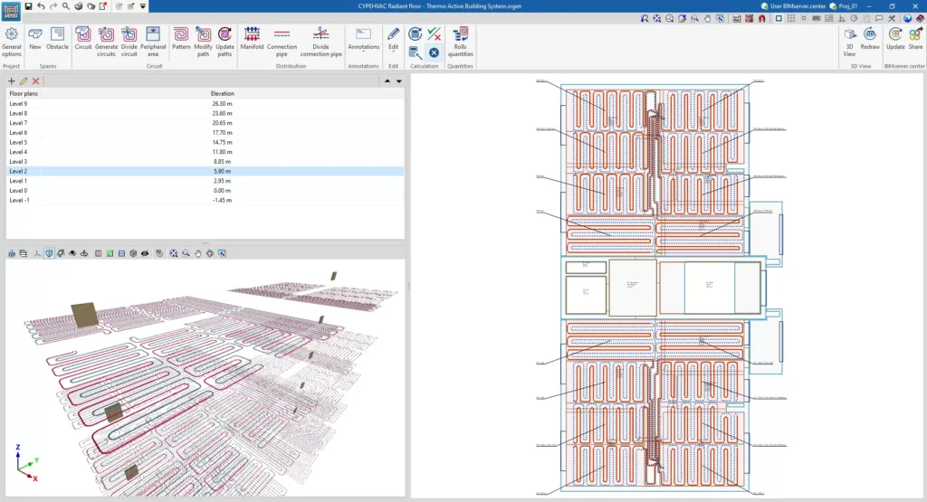
8. Automatic layout of radiant floor circuits in CYPEHVAC Radiant Floor
The CYPEHVAC Radiant Floor program can automatically generate the layout of the radiant floor circuits based on the thermal loads of the spaces and the design criteria defined by the user. The program analyses the spacing between pipes, the length of the circuits, the supply and return temperatures, as well as the pressure losses of each loop, and generates the system plans with their respective quantities.
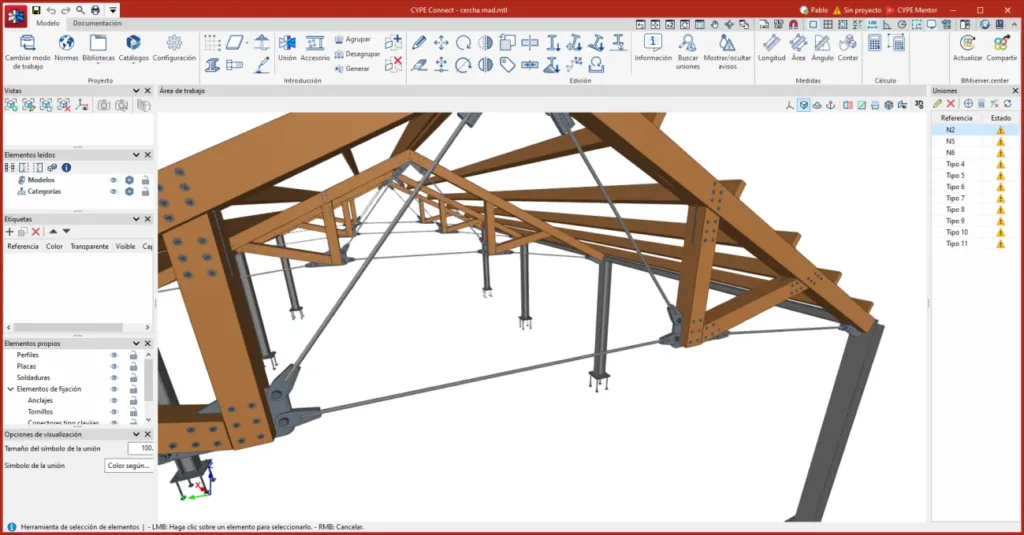
9. Interoperability between CYPE 3D, CYPE Connect and StruBIM Steel
The interoperability between CYPE 3D, CYPE Connect and StruBIM Steel results in a seamless and coordinated workflow for the design and fabrication of steelwork. The forces and combinations acting at each node of the structure analysed in CYPE 3D are automatically transferred to CYPE Connect, where the detailed analysis of the steel connections is carried out. In turn, the rotational stiffness values obtained in CYPE Connect are sent back to CYPE 3D to update the global structural behaviour, ensuring the consistency of the model. Finally, the model can be detailed in StruBIM Steel, including plates, welds, bolts, and exporting fabrication drawings and CNC files.
10. Integration of construction systems and real systems from AEC industry manufacturers
CYPE’s programs incorporate real manufacturers’ cataloguesand can work with commercially available products right from the design phase. This guarantees the feasibility of the project on site and facilitates communication between designers, installers and suppliers. For example, when selecting air-conditioning systems, real performance data is used for the thermal, electrical and acoustic analysis, which provides results that are in line with reality.
In short, all CYPE programs incorporate tools that automate tasks, avoid repeating processes and significantly increase the productivity of professionals in the dynamic AEC industry, so this list could be much longer, with a variety of examples such as these, all taken from real project situations.
Were you aware of all these features? Are you taking advantage of CYPE’s full potential?
If you still haven’t explored all these features or if they are not included in your user license, maybe now is the time to discover everything CYPE can do for you. Why not get in touch with CYPE now?
Для входа в аккаунт необходимо пройти простую процедуру регистрации.vodka casino регистрация через email для удобного и безопасного доступа к вашему аккаунту и широкому выбору игр.
Служба поддержки всегда готова помочь с любыми вопросами и проблемами.
Если вы занимаетесь производством и нуждаетесь в поставке лучших тугоплавких металлов, то ООО “РМС” – ваше решение. Наша компания занимается на сфере поставок тугоплавких металлов уже долгого времени, что позволяет нам поставлять только высококачественные металлы своим клиентам.
Основные преимущества ООО “РМС”:
1. Объемы поставок не имеют значения.
2. Обширный выбор тугоплавких металлов.
3. Все необходимые документы.
4. Круглосуточная поддержка.
Зачем тратить время на поиски на других сайтах, если rms-ekb.ru всегда готовы помочь?
В случае возникновения вопросов, наши эксперты всегда готовы вам помочь. Пишите прямо сейчас и убедитесь в достоинствах нашего сплава.
Если вы работаете в сфере производства и столкнулись с необходимостью в поставке лучших тугоплавких металлов, то ООО “РМС” – ваше спасение. Наша компания работает на области поставок тугоплавких металлов на протяжении многих лет, что дает нам возможность предлагать только проверенный материал своим клиентам.
Основные преимущества ООО “РМС”:
1. Мы поставим любые объемы материалов.
2. Большой ассортимент тугоплавких металлов.
3. Все необходимые документы.
4. Поддержка 24/7.
Зачем тратить время на поиски на других сайтах, если rms-ekb.ru всегда в вашем распоряжении?
В случае возникновения вопросов, наши эксперты всегда готовы вам помочь. Звоните прямо сейчас и убедитесь в преимуществах нашего редкого металла.
Если вы заняты в области индустрии и нуждаетесь в бесперебойной поставке лучших тугоплавких металлов, то ООО “РМС” — это ваше ключевой партнер. Наша компания профессионально работает в сфере поставок редких металлов на протяжении длительного срока, что гарантирует нам право отгружать только проверенный материал своим партнерам.
Реализуем любые объемы.
Внушительный выбор тугоплавких металлов.
Весь пакет сертификатов.
Сопровождение 24/7.
Зачем тратить время на поиски, если на rms-ekb.ru всегда лучшие условия?
При возникновении любых уточнений, наша команда профессионалов всегда к вашим услугам. Пишите прямо сейчас и убедитесь в бесспорных достоинствах нашего редкого металла.
Предлагаемые позиции:
Если вы представляете производственное предприятие и испытываете потребность в закупке первоклассных тугоплавких металлов, то ООО “РМС” — это ваше ключевой партнер. Наша компания лидирует в сфере поставок редких металлов уже десятилетий, что позволяет нам предоставлять только высококлассное сырье своим заказчикам.
Готовы к отгрузкам любой сложности.
Широкий ассортимент тугоплавких металлов.
Вся необходимая документация в наличии.
Сопровождение 24/7.
Зачем мониторить рынок, если на rms-ekb.ru всегда готовы помочь?
При возникновении любых уточнений, наша команда профессионалов всегда к вашим услугам. Пишите прямо сейчас и удостоверьтесь в уникальных преимуществах нашего продукта.
Предлагаемые позиции:


Получите профессиональную юрист консультация|бесплатную консультацию юриста|онлайн консультацию юриста|юридическую консультацию бесплатно|консультацию юриста бесплатно и разрешите свои юридические вопросы с уверенностью!
В современном мире юридические консультации стали неотъемлемой частью нашей жизни.
Для входа в аккаунт необходимо пройти простую процедуру регистрации.vodka casino регистрация через email для удобного и безопасного доступа к вашему аккаунту и широкому выбору игр.
Служба поддержки всегда готова помочь с любыми вопросами и проблемами.
Если вы занимаетесь производством и нуждаетесь в поставке лучших тугоплавких металлов, то ООО “РМС” – ваше решение. Наша компания занимается на сфере поставок тугоплавких металлов уже долгого времени, что позволяет нам поставлять только высококачественные металлы своим клиентам.
Основные преимущества ООО “РМС”:
1. Объемы поставок не имеют значения.
2. Обширный выбор тугоплавких металлов.
3. Все необходимые документы.
4. Круглосуточная поддержка.
Зачем тратить время на поиски на других сайтах, если rms-ekb.ru всегда готовы помочь?
В случае возникновения вопросов, наши эксперты всегда готовы вам помочь. Пишите прямо сейчас и убедитесь в достоинствах нашего сплава.
С уважением, команда ООО “РМС” !
Наша продукция:
Проволока из палладия и его сплавов Пд99.8 1.2 ГОСТ 18390 – 73
Если вы работаете в сфере производства и столкнулись с необходимостью в поставке лучших тугоплавких металлов, то ООО “РМС” – ваше спасение. Наша компания работает на области поставок тугоплавких металлов на протяжении многих лет, что дает нам возможность предлагать только проверенный материал своим клиентам.
Основные преимущества ООО “РМС”:
1. Мы поставим любые объемы материалов.
2. Большой ассортимент тугоплавких металлов.
3. Все необходимые документы.
4. Поддержка 24/7.
Зачем тратить время на поиски на других сайтах, если rms-ekb.ru всегда в вашем распоряжении?
В случае возникновения вопросов, наши эксперты всегда готовы вам помочь. Звоните прямо сейчас и убедитесь в преимуществах нашего редкого металла.
Команда ООО “РМС” на связи!
Наши товары:
Круг Х12Ф1 35.55 ГОСТ 7417 – 75
Если вы заняты в области индустрии и нуждаетесь в бесперебойной поставке лучших тугоплавких металлов, то ООО “РМС” — это ваше ключевой партнер. Наша компания профессионально работает в сфере поставок редких металлов на протяжении длительного срока, что гарантирует нам право отгружать только проверенный материал своим партнерам.
Реализуем любые объемы.
Внушительный выбор тугоплавких металлов.
Весь пакет сертификатов.
Сопровождение 24/7.
Зачем тратить время на поиски, если на rms-ekb.ru всегда лучшие условия?
При возникновении любых уточнений, наша команда профессионалов всегда к вашим услугам. Пишите прямо сейчас и убедитесь в бесспорных достоинствах нашего редкого металла.
Предлагаемые позиции:
Проволока стальная 600х180 мм S30800 ASTM A314
Если вы представляете производственное предприятие и испытываете потребность в закупке первоклассных тугоплавких металлов, то ООО “РМС” — это ваше ключевой партнер. Наша компания лидирует в сфере поставок редких металлов уже десятилетий, что позволяет нам предоставлять только высококлассное сырье своим заказчикам.
Готовы к отгрузкам любой сложности.
Широкий ассортимент тугоплавких металлов.
Вся необходимая документация в наличии.
Сопровождение 24/7.
Зачем мониторить рынок, если на rms-ekb.ru всегда готовы помочь?
При возникновении любых уточнений, наша команда профессионалов всегда к вашим услугам. Пишите прямо сейчас и удостоверьтесь в уникальных преимуществах нашего продукта.
Предлагаемые позиции:
Труба из жаропрочного сплава ХН50ВМТЮБ 351×30 ГОСТ 9941-81